|
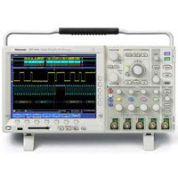
DPO3000 Series Oscilloscopes
DPO3012 • DPO3014 • DPO3032 • DPO3034 • DPO3052 • DPO3054
 Features & Benefits Features & Benefits |
Key Performance Specifications
- 500, 300, 100 MHz Bandwidth Models
- 2 and 4 Channel Models
- Sample Rates Up to 2.5GS/s on All Channels
- 5 Megasample Record Length on All Channels
- 50,000 wfm/s Maximum Waveform Capture Rate
- Suite of Advanced Triggers
Serial Bus Trigger and Decode
- I2C, SPI, CAN, LIN, RS232/422/485/UART Serial Triggering, Decode, and Analysis Options
Ease of Use Features
- Wave Inspector® Controls Provide Unprecedented Efficiency in Waveform Analysis
- 9 in. (229 mm) WVGA Widescreen Color Display
- USB 2.0 on Front Panel for Quick and Easy Data Storage
- USB 2.0 Device Port for Direct PC Control of Oscilloscope Using USBTMC
- Built-in Ethernet Port
- Plug ‘n’ Play Connectivity and Analysis Software Solutions
- e*Scope Remote Viewing and Control
- TekVPI® Probe Interface Supports Active, Differential and Current Probes for Automatic Scaling and Units
- Small Footprint and Lightweight – Only 5.4 in. (137mm) deep and 9 lbs. (4 kg)
|
 |
Applications |
- Embedded Design and Debug
- Investigation of Transient Phenomena
- Power Measurements
- Video Design and Debug
- Spectral Analysis
- Automotive Electronics Design and Debug
- Manufacturing Test and Quality Control
- Electro-mechanical Design and Analysis
- Bio-medical Product Development
- Industrial Control
DPO3000 Series Digital Phosphor Oscilloscopes
Feature-Rich Tools for Debugging Mixed Signal Designs
The Power to Solve Problems Quickly
The DPO3000 Series digital phosphor oscilloscopes (DPO) deliver the performance you need to visualize even your most demanding signals. Bandwidths range from 100MHz to 500MHz, and with all models offering a minimum of 5x over-sampling on all channels and sin(x)/x interpolation standard, you can be confident that even the fastest transient events will be captured and displayed accurately. The standard 5M record length on all channels enables you to capture long windows of signal activity while maintaining fine timing resolution. The 50,000 wfm/s waveform capture rate maximizes the probability of capturing elusive glitches and other infrequent events. |
The DPO3000 Series offers a variety of analytical solutions including cursors, 29 automatic measurements, statistics and waveform math. Despite a tiny footprint (only 5.4in.deep) and light weight (9lbs.), the DPO3000 Series offers exceptional performance, a large 9in.WVGA widescreen display and knob-per-channel vertical controls.
Perform Serial Debug for Common Standards
Serial Triggering and Analysis
One of the most common applications requiring long record length is serial data analysis in embedded system design. Embedded systems are literally everywhere. They can contain many different types of devices including microprocessors, microcontrollers, DSPs, RAM, EPROMs, FPGAs, A/Ds, D/As and I/O. These various devices have traditionally communicated with each other and the outside world using wide parallel buses. Today, however, more and more embedded systems are replacing these wide parallel buses with serial buses due to less board space required, fewer pins, lower power, embedded clocks, differential signaling for better noise immunity, and most importantly, lower cost. While serial buses have a large number of benefits, they also present significant challenges that their predecessors (parallel buses) did not. Debugging bus and system problems can be more difficult, because it is harder to isolate events of interest, and it is more difficult to interpret what is displayed on the oscilloscope screen. The DPO3000 Series addresses these problems.
Bus Display - Provides a higher level, combined view of the individual signals (clock, data, chip enable etc.) that make up your bus, making it easy to identify where packets begin and end and identifying sub-packet components such as address, data, identifier, CRC, etc.
Serial Triggering - Trigger on packet content such as start of packet, specific addresses, specific data content, unique identifiers, etc., on the popular serial interfaces I2C, SPI, CAN, LIN, and RS232/422/485/UART.
Bus Decoding - Tired of having to visually inspect the waveform to count clocks, determine if each bit is a 1 or a 0, combine bits into bytes and determine the hex value? Let the oscilloscope do it for you! The oscilloscope can decode each packet on the bus and display the value in hex, binary, decimal, or ASCII (depending on the standard) in the bus waveform.
Packet Decode Table - In addition to seeing decoded packet data on the bus waveform itself, you can view all captured packets in a tabular view much like you would see on a logic analyzer. Packets are time-stamped and listed consecutively with columns for each component (Address, Data, etc.).
Search - Serial triggering is very useful for isolating the event of interest, but once you’ve captured it and need to analyze the surrounding data, what do you do? In the past, users had to manually scroll through the waveform counting and converting bits and looking for what caused the event. With the DPO3000 Series, you can have the oscilloscope search through the acquired data for user-defined criteria including serial packet content. Each occurrence is high-lighted by a search mark. Rapid navigation between marks is as simple as pressing the Previous (←) and Next (→) buttons on the front panel.
Designed to Make Your Work Easier
Wave Inspector® Navigation
Imagine trying to efficiently use the Internet if search engines such as Google and Yahoo didn’t exist, web browser features such as Favorites and Links didn’t exist, or Internet Service Providers like AOL or MSN weren’t around. Now you know how most modern oscilloscope users feel when trying to actually use the long record length in their digital oscilloscope. Record length, one of the key specifications of an oscilloscope, is the number of samples it can digitize and store in a single acquisition. The longer the record length, the longer the time window you can capture with high resolution (high sample rate). The first digital oscilloscopes could capture and store only 500 points which made it very difficult to acquire all relevant information around the event being investigated. Over the years, oscilloscope vendors have provided longer and longer record lengths to meet market demands for long capture windows with high resolution to the point that most mid-range oscilloscopes either come standard with, or can be optionally upgraded to, multi-million-point record lengths. These million-point record lengths often represent thousands of screens worth of signal activity. While standard record lengths have increased greatly over the years and can now satisfy the vast majority of applications in the market-place, tools for effectively and efficiently viewing, navigating and analyzing long record length acquisitions have been sorely neglected until now. The DPO3000 Series addresses the need for working with long record lengths with the following innovative Wave Inspector controls:
Zoom/Pan - A dedicated, two-tier front-panel knob set provides intuitive control of both zooming and panning through acquired records. The inner knob adjusts the zoom factor (or zoom scale); turning it clockwise activates zoom and goes to progressively higher zoom factors, while turning it counter-clockwise results in lower zoom factors and eventually turning zoom off. The outer knob pans the zoom box across the waveform to quickly get to the portion of the waveform you are interested in. The outer knob also utilizes force-feedback to determine how fast to pan on the waveform. The farther you turn the outer knob, the faster the zoom box moves. Pan direction is changed by simply turning the knob the other way. No longer do you need to navigate through multiple menus to adjust your zoom view.
Play/Pause - A dedicated play/pause button on the front panel scrolls the waveform across the display automatically while you look for anomalies or an event of interest. Playback speed and direction are controlled using the intuitive pan knob. Once again, turning the knob further makes the waveform scroll faster and changing direction is as simple as turning the knob the other way.
User Marks - See something interesting on your waveform? Press the Set Mark button on the front panel to leave one or more “bookmarks” on the waveform. Navigating between marks is as simple as pressing the Previous (←) and Next (→) buttons on the front panel.
Search Marks - Don’t want to take the time to inspect the entire acquisition to find the event you’re looking for? The DPO3000 Series features robust waveform search that allows you to search through your long acquisition based on user-defined criteria. All occurrences of the event are highlighted with search marks and are easily navigated to, using the front panel's Previous (←) and Next (→) buttons. Search types include edge, pulse width, runt, logic, setup and hold, rise/fall time and I2C, SPI, CAN, LIN, RS232/422/485/UART packet content.
PC Connectivity and USB Mass Storage
The DPO3000 Series delivers an unprecedented new level of USB plug ‘n’ play operation and PC connectivity. A USB port on the front panel enables easy transfer of screenshots, instrument settings, and waveform data in the palm of your hand. Also, a second USB host port is on the rear of the instrument along with a USB device port which can operate as a USBTMC device port for controlling the oscilloscope remotely from a PC. An integrated 10/100 Ethernet port enables easy connection to networks. Acquiring data and measurements from the instrument is as simple as connecting a USB cable from the oscilloscope to the PC. Provided applications include NI LabVIEW SignalExpress™ Tektronix Edition, OpenChoice® Desktop and Microsoft Excel and Word toolbars enabling fast and easy direct communication with your Windows PC
TekVPI® Probing
The TekVPI probe interface sets the standard for ease of use in probing. TekVPI probes feature status indicators and controls, as well as a probe menu button right on the comp box itself. This button brings up a probe menu on the oscilloscope display with all relevant settings and controls for the probe. The TekVPI interface utilizes a new probe power management architecture enabling direct attachment of current probes. Finally, TekVPI probes can be controlled remotely via USB, GPIB or Ethernet, enabling more versatile solutions in ATE environments.
Additonal Application Support
Video Design and Development
Many video engineers have remained loyal to analog oscilloscopes, believing the intensity gradations on an analog display are the only way to see certain video waveform details. The DPO3000 Series fast waveform capture rate, coupled with its intensity-graded view of the signal, provides the same information-rich display as an analog oscilloscope, but with much more detail and all the benefits of digital scopes. With up to 500MHz band-width, four inputs, and a built-in 75Ω input termination, the DPO3000 Series provides ample performance for analog and digital video use.
Finally, the DPO3000 Series video functionality is further extended with the optional DPO3VID video application module. DPO3VID provides the industry’s most complete suite of HDTV and custom (non-standard) video triggers
Digital Design and Debug
Today’s digital designs often require careful layout of circuitry to guarantee consistent time alignment between clocks on circuit boards. Small differences in delays caused by routing issues or inconsistent propagation time across a circuit board can cause numerous issues with the operation of digital functional blocks. The DPO3000 Series can assist in finding those small phase shifts that occur between clocks as they migrate across a design. XY display of two clocks can give a quick visual indication of a phase difference between them. Frequency differences can also quickly be seen. This can be very helpful when determining how effective clock multiplier or divider networks are working.
The interoperability of the DPO3000 Series oscilloscope with the Tektronix TLA5000 Series logic analyzer made possible by Tektronix’ Integrated View (iView™) feature enables digital designers to solve signal integrity challenges and effectively debug and verify their systems more quickly and easily. The iView feature fully integrates the industry-leading performance and measurement accuracy of a Tektronix oscilloscope with the multi-channel and powerful triggering capabilities of a Tektronix logic analyzer. This integration allows designers to view time-correlated digital and analog data in the same display window, and isolate analog characteristics of digital signals that are causing failures in their systems. No user calibration is required. And, once set up, the iView feature is completely automated. The result – an integrated tool set for digital design and troubleshooting.
Characteristics/Specs
|
|
VerticalSystem |
DPO3012 |
DPO3014 |
DPO3032 |
DPO3034 |
DPO3052 |
DPO3054 |
|
Input Channels |
2 |
4 |
2 |
4 |
2 |
4 |
|
Analog Bandwidth (-3dB) |
100 MHz |
100 MHz |
300 MHz |
300 MHz |
500 MHz |
500 MHz |
|
Calculated Rise Time
5 mV/div (typical) |
3.5ns |
3.5ns |
1.17 ns |
1.17 ns |
700 ps |
700 ps |
|
Hardware Bandwidth Limits |
20 MHz or 150 MHz |
|
Input Coupling |
AC, DC, GND |
|
Input Impedance |
1 MΩ ±1%, 75 Ω ±1%, 50 Ω ±1% |
|
Input Sensitivity Range, 1MΩ |
1 mV/div to 10 V/div |
|
Input Sensitivity Range, 75Ω,50Ω |
1 mV/div to 1 V/div |
|
Vertical Resolution |
8 bits (11 bits with Hi-Res) |
|
Max Input Voltage,1MΩ |
300 VRMS with peaks ≤±450 V |
|
Max Input Voltage, 75Ω,50 Ω |
5 VRMS with peaks ≤±20 V |
|
DC Gain Accuracy |
±1.5% with offset set to 0 V |
|
OffsetRange |
1MΩ |
50Ω, 75Ω |
|
1 mV/div to 99.5mV/div |
±1V |
±1V |
|
100mV/div to 995mV/div |
±10V |
±5V |
|
1 V/div |
±100V |
±5V |
|
1.01 V/div to 10 V/div |
±100V |
NA |
|
Channel-to-Channel Isolation
(Any Two Channels at Equal Vertical Scale) |
≥ 100:1 at ≤100 MHz and ≥ 30:1 at > 100MHz up to the rated BW |
|
Horizontal System |
All DPO3000 Models |
|
Maximum Sample Rate (all channels) |
2.5 GS/s |
|
Maximum Record Length (all channels) |
5 M points |
|
Maximum Duration of Time Captured at Highest Sample Rate (all channels) |
2 ms |
|
Time base Range (S/div) |
1 ns to 1000 s |
|
Time base Delay Time Range |
- 10 divisions to 5000 s |
|
Channel-to-Channel Deskew Range |
±100 ns |
|
Timebase Accuracy |
±10 ppm over any ≥ 1 ms interval |
|
Trigger System |
|
Main Trigger Modes |
Auto, Normal, and Single |
|
Trigger Coupling |
DC, AC, HF reject (attenuates>50 kHz), LF reject (attenuates <50 kHz), noise reject (reduces sensitivity) |
|
Trigger Holdoff Range |
20 ns to 8 s |
|
Sensitivity |
|
Internal DC Coupled |
0.4 div DC to 50 MHz, increasing to 1 div at rated bandwidth |
|
External (Auxiliary Input) |
200mV from DC to 50MHz increasing to 500mV at 250MHz |
|
Trigger Level Range |
|
Any Channel |
±8 divisions from center of screen |
|
External (auxiliary input) |
±8V |
|
Acquisition Modes |
|
Sample |
Acquire sampled values |
|
Peak Detect |
Captures narrow glitches at all real-time sampling rates |
|
Averaging |
From 2 to 512 waveforms included in average |
|
Envelope |
Min-max envelope reflecting Peak Detect data over multiple acquisitions |
|
Hi-Res |
Real-time boxcar averaging reduces random noise and increases resolution |
|
Roll |
Scrolls waveforms right to left across the screen at sweep speeds slower than or equal to 40ms/div |
|
Trigger Modes |
|
Edge |
Positive or negative slope on any channel or front panel auxiliary input. Coupling includes DC, AC, HF reject, LF reject and noise reject |
|
Pulse Width |
Trigger on width of positive or negative pulse that are >, <, = or ≠ a specified period of time |
|
Runt |
Trigger on a pulse that crosses one threshold but fails to cross a second threshold before crossing the first again |
|
Logic |
Trigger when any logical pattern of channels goes false or stays true for specified period of time. Any input can be used as a clock to look for the pattern on a clock edge. Pattern (AND, OR, NAND, NOR) specified for four input channels defined as High, Low or Don’t Care. |
|
Setup and Hold |
Trigger on violations of both setup time and hold time between clock and data present on any two input channels |
|
Rise/Fall Time |
Trigger on pulse edge rates that are faster or slower than specified. Slope may be positive, negative or either. |
|
Video |
Trigger on all lines, odd, even or all fields on NTSC, PAL and SECAM video signals |
|
Extended Video (optional) |
Trigger on 480p/60, 576p/50, 720p/30, 720p/50, 720p/60, 875i/60, 1080i/50, 1080i/60, 1080p/24, 1080p/24sF, 1080p/25, 1080p/30, 1080p/50, 1080p/60 and custom bi-level and tri-level sync video standards |
|
I2C (optional) |
Trigger on Start, Repeated Start, Stop, Missing ACK, Address (7 or 10 bit), Data or Address & Data on I2C buses up to 3.4 Mb/s |
|
SPI (optional) |
Trigger on SS, MOSI, MISO or MOSI & MISO on SPI buses up to 10.0 Mb/s |
|
CAN (optional) |
Trigger on Start of Frame, Frame Type (data, remote, error, overload), Identifier (standard or extended), Data, Identifier and Data, End of Frame, Missing ACK, or Bit Stuffing Error on CAN signals up to 1 Mb/s. Data can be further specified to trigger on ≤, <, =, >, ≥ or ≠ a specific data value. User-adjustable sample point is set to 50% by default. |
|
LIN (optional) |
Trigger on Sync, Identifier, Data, Id & Data, Wakeup Frame, Sleep Frame, Error up to 100 kb/s |
|
RS-232/422/485/UART (optional) |
Trigger on Tx Start Bit, Rx Start Bit, Tx End of Packet, Rx End of Packet, Tx Data, Rx Data, Tx Parity Error, and Rx Parity Error |
|
Trigger Delay by Time |
4 ns to 8 s |
|
Trigger Delay by Events |
1 to 9,999,999 events |
|
Waveform Measurements |
|
Cursors |
Waveform and Screen |
|
Automatic Measurements |
29, of which up to four can be displayed on screen at any one time.
Measurements include: Period, Frequency, Delay, Rise Time, Fall Time, Positive Duty Cycle, Negative Duty Cycle, Positive Pulse Width, Negative Pulse Width, Burst Width, Phase, Positive Overshoot, Negative Overshoot, Peak to Peak, Amplitude, High, Low, Max, Min, Mean, Cycle Mean, RMS, Cycle RMS, Rising Edge Count, Falling Edge Count, Po | | |