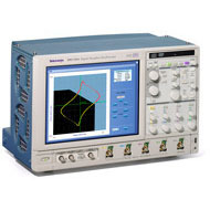
| 상품명 | DPO-7054 / Digital Phosphor Oscilloscopes |
|---|---|
| 제조사 | Tektronix |
| 판매가 | 전화문의 |
| 수량 |   |
배송주기

| 옵션선택 |
(최소주문수량 1개 이상 / 최대주문수량 0개 이하)
사이즈 가이드수량을 선택해주세요.
위 옵션선택 박스를 선택하시면 아래에 상품이 추가됩니다.
| 상품명 | 상품수 | 가격 |
|---|---|---|
| DPO-7054 / Digital Phosphor Oscilloscopes |


|
전화문의 ( |
할인가가 적용된 최종 결제예정금액은 주문 시 확인할 수 있습니다.
Features & Benefits
Applications
Unmatched Performance for Greater Insight Into Your Design to Get Your Work Done FasterThe DPO7000 Series are the new generation of real-time digital phosphor oscilloscopes and are the industry’s best solution to the challenging signal integrity issues faced by designers verifying, characterizing, debugging and testing sophisticated electronic designs. The family features exceptional performance in signal acquisition and analysis, operational simplicity and unmatched debugging tools to accelerate your day-to-day tasks. The largest screen in the industry and the intuitive user interface provide easy access to the maximum amount of information. Unmatched Acquisition PerformanceSignal Fidelity of Tektronix Oscilloscopes Ensures Confidence in Your Measurement Results
 Zoom in on four areas of interest simultaneously to compare them
 Tektronix Active probes achieve high-speed signal acquisition and measurement fidelity Unmatched VersatilityGet the Most of Your Oscilloscope by Fully Controlling its Waveform Acquisition and Display ParametersYou have the choice of three horizontal time base modes of operations. If you are simply doing signal exploration and want to interact with a lively signal, you will use the Automatic or interactive default mode that provides you with the liveliest display update rate. If you want a precise measurement and the highest real-time sample rate that will give you the most measurement accuracy, then the Constant Sample Rate mode is for you. It will maintain the highest sample rate and provide the best real-time resolution. The last mode is called the Manual mode because it ensures direct and independent control of the sample rate and record length.  3 modes of operation of the horizontal time base With the MyScope® Feature, Create Your Own Control Windows With Only the Controls, Features, and Capabilities that You Care AboutEasily create your own personalized "toolbox" of oscilloscope features in a matter of minutes using a simple, visual, drag and drop process. Once created, these custom control windows are easily accessed through a dedicated MyScope button and menu selection on the oscilloscope button/menu bar, just like any other control window. You can make an unlimited number of custom control windows, enabling each person who uses the oscilloscope in a shared environment, to have their own unique control window. MyScope control windows will benefit all oscilloscope users, eliminating the ramp-up time that many face when returning to the lab after not using an oscilloscope for a while, and enables the power user to be far more efficient. Everything you need is found in one control window rather than having to constantly navigate through menu after menu to repeat similar tasks.  Drag and drop menu items of interest to create the MyScope control window With OpenChoice® Software, Customize Your Test and Measurement System with Familiar Analysis ToolsThe analysis and networking features of OpenChoice software add flexibility to Tektronix' Windows XP oscilloscopes: Using the fast embedded bus, waveform data can be moved directly from acquisition to analysis applications on the Windows desktop at much faster speeds than conventional GPIB transfers. Tektronix’ implementation of industry standard protocols, such as TekVISA™ interface and ActiveX controls, are included for using and enhancing Windows applications for data analysis and documentation. IVI-COM instrument drivers are included to enable easy communication with the oscilloscope using GPIB, serial data, and LAN connections from programs running on the instrument or an external PC. Or, use the Software Developer’s Kit (SDK) to help create custom software to automate multi-step processes in waveform collection and analysis with Visual BASIC, C, C++, MATLAB, LabVIEW, LabWindows/CVI and other common Application Development Environments (ADE). Integration of the oscilloscope with external PCs and non-Windows hosts is also supported by the DPO7000 Series software solutions. In addition, the OpenChoice architecture provides a comprehensive software infrastructure for faster, more versatile operations. Data transfer programs, such as the Excel or Word toolbar, are used to simplify analysis and documentation on the Windows desktop or on an external PC.  Capture data into Microsoft Excel using the unique Excel toolbar, and create custom reports using the Word toolbar Accelerate the Debug of Complex Electrical DesignsFastAcq Acquisition Mode Expedites Debugging by Clearly Showing ImperfectionsMore than just color-grading, FastAcq enabled by Tektronix proprietary DPX® acquisition technology, captures signals up to more than 250,000 waveforms per second on all 4 channels simultaneously, dramatically increasing the probability of discovering infrequent fault events. And with a simple turn of the intensity knob you can clearly see “a world others don’t see,” because frequency of occurrence is color-coded. Some oscilloscope vendors claim high waveform capture rates for short bursts of time, but only the DPO7000 Series, enabled by DPX technology, can deliver these fast waveform capture rates on a sustained basis — saving minutes, hours, or even days by quickly revealing the nature of faults so sophisticated trigger modes can be applied to isolate them.  Maximize the probability of capturing elusive glitches and other infrequent events with FastAcq acquisition mode. The Ability to Trigger an Oscilloscope on Events of Interest is Paramount in Complex Signal Debug and ValidationWhether you’re trying to find a system error or need to isolate a section of a complex signal for further analysis, Tektronix’ Pinpoint™ triggering provides the solution. The Pinpoint trigger system uses Silicon Germanium (SiGe) technology to provide trigger sensitivity of up to the bandwidth of the instrument, and allows selection of most trigger types on both A and B trigger circuits. It can capture very narrow glitches with very little trigger jitter. Other trigger systems offer multiple trigger types only on a single event (A event), with delayed trigger (B event) selection limited to edge type triggering and often do not provide a way to reset the trigger sequence if the B event doesn’t occur. But Pinpoint triggering provides a full suite of advance trigger types on both A and B triggers with Reset triggering to begin the trigger sequence again after a specified time, state or transition so that even events in the most complex signals can be captured. Other oscilloscopes typically offer less than 20 trigger combinations; Pinpoint triggering offers over 1400 combinations, all at full performance. With Enhanced Triggering, you can choose to compensate for the difference in time there is between the trigger path and the display path and eliminate virtually any trigger jitter at the trigger point. In this mode, the trigger point can be used as a measurement reference.  Isolate glitches down to 200ps wide  Isolate set-up and hold violations down to 360ps Trigger on the Most Relevant Bit Sequence of the Industry Standard Serial BusI2C (Inter-Integrated Circuit) triggering is a standard feature and includes Start condition, Missing Acknowledge, Restart, Data Read, Address and/or Data Frame, in a 10 bit or 7 bit format with a specific selection to choose whether or not to include the R/W bit. SPI (Serial Peripheral Interface) triggering is a standard feature and includes triggering on a data pattern within a user-definable frame. RS-232 triggering is a standard feature. CAN (Controller Area Network) triggering is an optional feature (Opt. LSA) and includes synchronization to the Start or End of a CAN frame on any CAN high or CAN low signal, triggering on Type of Frame (Data, Remote, Overload), Identifier, Data, Missing Acknowledge, and Bit Stuffing error.  Easily trigger on a specific I2C address Analog HDTV/EDTV Triggering for emerging standards like 1080i, 1080p, 720p and 480p as well as standard video triggering on any line within a field, all lines, all fields, odd or even fields for NTSC, SECAM and PAL video signals. In addition, IRE and mV graticules can be selected for easier measurements and visual inspection. This is a standard feature.  Triggering on an analog HDTV tri-level sync signal and examining horizontal blanking interval To debug serial architectures, use the serial pattern triggering option for NRZ serial data stream with built-in clock recovery (available on models DPO7254 and DPO7354 only). The instrument can recover the clock signal, identify the transitions, and decode characters and other protocol data. With the combination of the Serial Trigger and Protocol Decode software, you can see the captured bit sequences decoded into their words for convenient analysis (for 8b/10b and other encoded serial data streams), or you can set the desired encoded words for the serial pattern trigger to capture. This serial trigger option covers NRZ serial standards up to 1.25Gb/s.  Serial pattern triggering to debug pattern dependent issues Pattern Lock Triggering adds a new dimension to NRZ serial pattern triggering by enabling the oscilloscope to take synchronized acquisitions of a long serial test pattern with outstanding time base accuracy. Pattern lock triggering can be used to remove random jitter from long serial data patterns. Effects of specific bit transitions can be investigated, and averaging can be used with mask testing. This feature is included as part of Option PTM on the DPO7254 and 7354 models. Large 12.1-inch XGA Display ScreenThe DPO7000 Series has the largest display in the industry with a 12.1” XGA touch screen that gives up to 15% more waveform display than other oscilloscope series in its class.  How does 12.1" display compare to the display size of other oscilloscopes? 10 vertical divisions give you 25% more vertical measurement resolution. Unmatched UsabilityThe TekVPI™ probe interface provides versatility and ease of use enabled by intelligent bi-directional oscilloscope-to-probe communication. The DPO7000 Series are fast-responding instruments and contain a comprehensive suite of features, such as a touch-screen, shallow menu structures, intuitive graphical icons, knob per channel vertical controls, support for right mouse clicks, mouse wheel improvements, saving of waveforms and measurements available in Preview mode, Export/Save/Recall menu improvements. Interoperability with Logic Analyzers for Digital Design and DebugTektronix' Integrated View (iView™) data display enables digital designers to solve signal integrity challenges and effectively debug and verify their systems more quickly and easily. This integration allows designers to view time-correlated digital and analog data in the same display window, and isolate the analog characteristics of the digital signals that are causing systems failures. No user calibration is required. And, once set up, the iView feature is completely automated.  An integrated toolset for digital design and troubleshooting. More Insight into Your Complex Electrical Design for Characterization and Compliance TestingSuch as a simple math expression, waveform mask testing, a pass/fail compliance test, event searching, event marking or a custom application that you develop yourself, the DPO7000 Series Oscilloscopes offer the industry’s most comprehensive set of analysis and compliance tools. A Wide Range of Built-in Advanced Waveform Analysis ToolsWaveform cursors make it easy to measure trace-to-trace timing characteristics, while cursors that link between YT and XY display modes make it easy to investigate phase relationships and Safe Operating Area violations. Select from 53 automatic measurements using a graphical palette that logically organizes measurements into Amplitude, Time, Combination, Histogram, and Communications categories. Gather further insight into your measurement results with statistical data such as mean, min, max, standard deviation, and population. Define and apply math expressions to waveform data for on-screen results in terms that you can use. Access common waveform math functions with the touch of a button. Or, for advanced applications, create algebraic expressions consisting of live waveforms, reference waveforms, math functions, measurement values, scalars and user adjustable variables with an easy-to-use calculator-style editor. FFT - To analyze your signal in the spectral domain, use the basic spectral (provides you with the best parameter), or use advanced spectral with the manual time base horizontal mode (to directly control the frequency span, center frequency and resolution bandwidth).  Basic spectral UI control window Filtering - Enhance your ability to isolate or remove some important component of your signal (noise or specific harmonics of the signal) by creating your own filters, or using the filters provided as standard with the instrument. A Breadth of Optional Packages to Extend Waveform Analysis Even FurtherJitter and Timing Measurement and Analysis Package (Opt. JA3 or JE3) - Tight timing margins demand stable, low jitter designs. This software option extends the oscilloscope capability by making jitter measurements over contiguous clock cycles from every valid pulse in a single-shot acquisition. Multiple measurements and trend plots quickly show system timing under variable conditions. This analysis package is available as Opt. JA3 or Opt. JE3 on the DPO7000 Series. JE3 provides a subset of the measurements.  Jitter and Timing Measurement Advanced Event Search and Mark (Opt. ASM) - Event Search and Mark will relieve the user from the tedious task of examining data by highlighting important events, skipping the unimportant ones, and enhancing the comprehension of event relationships. You can navigate between the events of interest effortlessly. A basic event (edge –only) search and mark is provided as a standard feature; and support for more advanced event types like transition, setup and hold or logic pattern, is provided with the ASM option.  Accelerating the research of specific events in an acquired waveform. Limit Testing (Opt. LT) - This feature consists of comparing an acquired waveform to boundaries. These boundaries are typically defined by the user to specify a tolerance band around a reference waveform. If any part of the acquired waveform falls outside of the limit, the software returns a failure message and the location of the failure is shown on the waveform. Communications Mask Testing (Opt. MTM) - This feature provides a complete portfolio of masks for verifying compliance to serial communications standards. It supports 156 Standards Masks –
CAN and LIN Timing and Protocol Decode Software (Opt.LSA) - When you need to ensure seamless and reliable operation of a CAN or LIN network, this option enables CAN bus triggering and provides the solution to measure oscillator tolerance, propagation delay, and simultaneously decode CAN and LIN messages, with the protocol leveraging the trigger capabilities. This option is offered on DPO7354, DPO7254, DPO7104 and DPO7054 as Opt. LSA.  CAN and LIN Timing and Protocol Decode Optional Power Measurement and Analysis (Opt.PWR) - Analyze power dissipation in power supply switching devices and magnetic components, and generate detailed reports in customizable formats. The HiRes acquisition mode delivers greater than 8 bits of vertical resolution on single-shot or repetitive signals at bandwidth up to 125MHz. The powerful and flexible measurements, math, and math-on-math capabilities make it an ideal solution for performing power measurements, such as voltage, current, instantaneous power and energy, for power device designers. The new TekVPI™ interface provides smart communication between the oscilloscope and the probe. TekVPI probe interface also provides more power to the probe interface, allowing customers to directly connect current probes to the front of the oscilloscope.  Power Measurement and Analysis Optional Ethernet (Opt. ET3) - Provides compliance testing for 10/100/1000Base-T signals.  Ethernet compliance testing Optional USB (Opt.USB) - Provides compliance testing for USB2.0signals.
CharacteristicsVertical System
| ||||||||||||||||||||||||||
상품의 사용후기를 적어주세요.
게시물이 없습니다
상품에 대해 궁금한 점을 해결해 드립니다.
게시물이 없습니다


법인명(상호) : 주식회사 디앤에이코리아 대표자(성명) : 이인호 사업자 등록번호 안내 : [113-86-72293] 통신판매업 신고 제2013-서울구로-0536호 [사업자정보확인]
전화 : 070-4106-3405 팩스 : 02-2625-3405 주소 : 152721 서울 구로구 구로2동 중앙유통단지 나동 2316
개인정보보호책임자 : 이인호(2453405@naver.com)
Contact 2453405@naver.com for more information.
Copyright © (주)디앤에이코리아. All rights reserved.

![]()